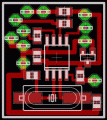
Detects the presence of a live mains conductor
Minimum parts counting
Parts:
C1 100nF 63V Polyester or Ceramic Capacitor
D1 Red LED (any type)
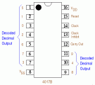
IC1 4017 Decade counter with 10 decoded outputs IC
P1 SPST Pushbutton
B1 3V Battery (two 1.5V AA or AAA cells in series etc.)
Sensing probe__3 to 15 cm. long, stiff insulated piece of wire
Circuit operation:
If the unit is brought close to a live conductor (insulated, and even buried in plaster) capacitive coupling between the live conductor and the probe clocks the counter, and causes the LED to flash 5 times per second, because the 4017 IC divides the mains 50Hz frequency by 10.
When remote from a live line, the unit stops counting, the LED resulting permanently off.
Notes:
Sensitivity can be varied using a more or less long sensing probe.
Due to 3V operation, the LED's current limiting resistor can be omitted.
Author: RED Free Circuit Designs
Email:
Website: http://www.redcircuits.com

 Audio
Audio


