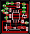
I call this the "huntron circuit" because a company by that name made a similar device. It is useful for trouble-shooting. I used it with digital PC boards where I did not have a schematic, or even know how it worked. I recorded the patterns found on a good board and compared them with the patterns from a defective board. Any low power 12 volt transformer will work, the resistors are ¼ watt.
Author: Russell Kincaid
Email:
Website: http://www.electronics-lab.com

 Audio
Audio


