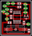
This is a simple XTal tester circuit. T1 and XTal have formed an oscillator. C1 and C2 are voltage divider for oscillator. if the XTal is safe, the oscillator will work well and its output voltage will be rectified by C3, C4, D1 and D2, then T2 will run and LED will light. The circuit is suitable to test 100KHz - 30MHz Xtal.
Author: 303 circuits, Elektor Electronics
Email:
Website: http://www.electronics-lab.com

 Audio
Audio


