[url=projects/150/servo.pdf]
click here to download schematic in pdf [/url]
This is a simple servo tester which will comprehensively test the capabilities of almost any modern servo. It has two pushbuttons, CENTRE and SWEEP and a potentiometer which works as follows:
- CENTRE Does exactly that, centers the servo, afterwards the potentiometer determines position.
- SWEEP Sweeps the servo back and forth at a rate determined by the potentiometer setting.
The PIC uses its internal timer to set up a constant frame duration of 20ms and the on/off ratio is set by the user.
Have Fun
Ed
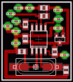
PCB board (download it below)
suggested panel decal
Parts
R1 = 1K
R2 = 10K
R3 = 82R
R4 = 10K
R5 = 5K potentiometer
C1 = 27pF
C2 = 27pF
C3 = 100nF
D1 = 4,7V zener diode
Q1 = 10MHz crytal
IC1 = PIC12F675
Download assembly code (.asm)
Download PCB in Eagle format (.br )
Author: EdwardM
Email: maxwatted@yahoo.co.uk
Website: http://www.electronics-lab.com

 Audio
Audio


