Description
This launch controller can be used with low voltage battery igniters, which fire rocket engines in model rockets such as the Estes range. These circuits are electrical, only switches and contacts are involved. First the circuit for a single rocket:
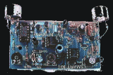
The only thing to note here is that this controller uses "C" cells, providing more current than "AA" batteries and that the push button switch has contacts rated 1 amp or higher. The wire to the igniter is isolated via a 3.5 inch jack plug and socket. Connect the igniter, then plug in to control box and then press button, making sure you are the recommended distance away. Below is an internal and external picture of my controller:-
Ok, does anyone think my grass needs cutting? Moving on to the multi launch controller:-
Once again, nothing too complicated. The single pole rotary switch has contacts rated 1 amp so can easily handle the 400 mA of current that the igniter takes. Here three rockets can be launched by rotating the switch. The Green LED provides continuity between battery,igniter and wiring. This extinguishes as the launch switch is pressed. Once again, observe safety precautions.
Mission Critical:
Heres a story about my own Estes space shuttle, on its one and only mission. This is what happens when you're too eager to get a rocket flying and don't pay attention to balance. It was a late November afternoon in 1998 when I first launched the shuttle. Lift off was perfect, no wind, clear skies (doesn't sound at all like England), and the rocket motor was a C6-5. At launch, the rocket motor fired, though lift off acceleration was not as good as I expected, I blame too much paint and excess weight). As my rocket reached apogee, (estimated height about 100 meters) and acceleration became zero there was no immediate separation between the shuttle and main fuel tank. There was of course a delay of 5 seconds between the rocket engine blowing its ejection charge. Five seconds is a long time too wait, especially when the forces excerted of gravity take hold. At 9.8 meters/second, the rocket plunged towards earth losing at least half its height. Then, thankfully the ejection charge blew, separation was achieved the the main fuel tank with SRB's drifted slowly down to earth on its parachute. However all was not well with the shuttle. It was only after separation that I realized there was too much nose weight (hence a heavy lift up and not enough height). The shuttle did glide, but only at about 45 degrees downward, picking up speed until eventually it crash landed in some soft mud. Luckily it survived the impact, I cleaned it up but have not yet removed the nose cone to balance the shuttle. I like it as an ornament anyway.
Author:
Email:
Website: http://www.electronics-lab.com

 Audio
Audio


