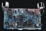
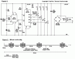
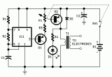
This circuit uses a 1458 dual op-amp to form a radar detector. C1 is the detector of the radar signal. The first op-amp forms a current-to-voltage converter and the second op-amp buffers the output to drive the piezo transducer. R5 sets the switching threshold of the second op-amp; normally it is adjusted so that the circuit barely triggers on background noise, then it's backed off a bit. The response of the circuit may be tuned by adjusting the length of the leads on C1. For typical road-radar systems, the input capacitor's leads should be about 0.5 to 0.6 inches long.
Author: "Radio-Electronics" Magazine, Jul,86 issue (C) Copyright Gernsback Publications, Inc., 1986
Email:
Website: http://www.electronics-lab.com

 Audio
Audio


